Machining processes are the most common ways to produce a component or a part by removing excess material from a block of material. The quality of the part depends on how stable the process is. The stability here has two components: one involving the physical machine-tool system and the other involving the machining process. Both factors have to be sufficiently understood to make the machining process efficient and optimized. In this first article, let us focus on the machine-tool system.
The machine-tool system consists of several components that are put together to work simultaneously to remove material. A typical machine tool has a solid base, an X-Y moving table, fixture attached to the table to hold the workpiece, workpiece material, a frame, spindle attached to the frame, a tool holder and a cutting tool. This machine tool system is designed in such a way that it could accurately and repeatedly maintain its relative position between the cutting tool and the workpiece material. This means that the system should be stiff enough, i.e. should have certain resistance to deform under certain applied loads during the machining process. The stiffness of the machine-tool system is essentially a combination of the stiffness of each component forming a loop, called the stiffness loop, as shown in the figure below.
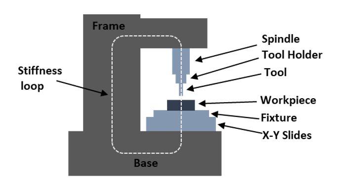
Machine-tool stiffness loop
Loop stiffness
Furthermore, there are two types of loop stiffness: static loop stiffness and dynamic loop stiffness. Static loop stiffness of the system is the ability of the system to withstand static or quasi-static loads, such as its own weight or standard cutting loads. A typical machine tool is designed for a certain loop stiffness, as required by the process, and it is fairly easy to calculate. A heavy cutting process requires a loop stiffness of 500 N/µm, while the smaller ones have around 10 N/µm. Dynamic loop stiffness on the other hand, should resist dynamic loads, i.e. dynamically changing forces with certain amplitude and frequency. This is measured using an excitation load equal to the damped natural frequency of the machine-tool system.
The deviation in the relative position between the cutting tool and the work piece occurs when the loop stiffness is changed or modified. For example, vibrations from external sources (from a machine nearby) can interfere with the resonant frequency of one of the components in the machine-tool system. Vibrations could also arise from an internal source within the machine-tool system, like machine spindle bearing wear or from linear drives. So it is important to understand the source of these vibrations that could modify the dynamic loop stiffness of the machine-tool system.
We will look into various sources of vibrations that could affect the quality of the process and the products in the coming weeks. Follow us for more updates!
Online platform
On Sirris's 'modelgebaseerdbewerken' online platform you can already evaluate stability of different parameters of you process. You can also access models like milling economics model and use them to optimise your machining processes. Access to the platform is free of charge, but you need to register. You will also find the necessary explanations about working with the models on the platform, but be sure to keep an eye on the Sirris agenda, because we will be organising both physical and online events like webinars and workshops.
Would you like to know more? Get in touch with us!
The online platform is part of the COOCK project 'Model-based processing', which was launched with support from VLAIO.